
Cold Room Defrost Scheduling: Clock, Runtime or Demand?
Choose and validate a cold-room defrost schedule using elapsed time, compressor runtime, clock events or demand signals—without confusing start and stop logic.
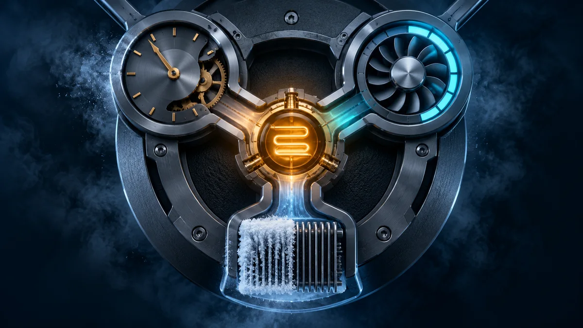
A cold room defrost schedule decides when a defrost cycle may start. It does not decide when the cycle should end. That distinction matters: start logic manages frost risk and operational timing, while termination temperature and maximum defrost time control the active cycle.
Controllers can count ordinary elapsed time, count only compressor runtime, start at selected clock times, or use measured conditions to request defrost. None is automatically best. The right strategy depends on the evaporator, moisture load, door activity, operating pattern, available sensors, and what evidence the controller can record.
This guide provides a selection and commissioning framework without prescribing a universal interval. For the other half of the sequence, see defrost termination temperature and maximum time. For the recovery stage, read the guide to evaporator fan delay after defrost.
Separate four questions before changing a parameter
A reliable defrost specification answers four different questions:
- What creates a request? Elapsed time, compressor runtime, a clock event, a sensor-derived condition, a remote command, or a manual service action.
- What permits the request to start? Minimum spacing, coil-temperature limits, compressor or valve state, door state, system coordination, and safety interlocks.
- What ends active defrost? Evaporator temperature, maximum duration, an external input, or an approved protective condition.
- What happens afterward? Drip-off, refrigeration restart, fan release, alarm bypass, and return to normal control.
Changing only the interval can hide a problem elsewhere in this chain. A short interval cannot correct a loose probe, failed heater, blocked drain, poor airflow, or a door that remains open.
Compare the main defrost-start strategies
| Strategy | What advances the trigger | Useful when | Main verification risk |
|---|---|---|---|
| Elapsed interval | Wall time since the previous defined event | The load pattern is stable and the controller is simple | It keeps counting during light use unless the logic says otherwise |
| Compressor runtime | Accumulated cooling operation | Frost exposure broadly follows refrigeration duty | The counter origin, reset rules, and qualifying compressor state may be misunderstood |
| Real-time clock | Approved calendar times | Defrost must fit loading, access, tariff, or coordinated system windows | Clock accuracy, timezone, power recovery, and schedule ownership become part of commissioning |
| Demand signal | A validated sensor or calculated condition | The system has suitable sensing and a proven algorithm | A wrong probe, threshold, fallback, or fault response can suppress or over-call defrost |
These strategies can be combined. For example, a controller may use a minimum interval before accepting a demand signal and a maximum interval as a fallback. The combination and priority must be read from the actual controller documentation, not inferred from a menu label.
Elapsed-time intervals: simple but independent of cooling duty
An elapsed-time controller starts from a defined reference and counts ordinary time whether or not the compressor is running. The official Danfoss EET refrigeration-controller guide explicitly distinguishes elapsed-time counting from accumulated compressor-runtime counting. It also separates minimum and maximum defrost intervals from termination temperature and maximum defrost duration.
Elapsed time can be appropriate when operating conditions are repeatable and the equipment documentation supports that method. Its simplicity also makes the schedule easy to audit. But the commissioning record still needs to define:
- whether the interval is measured start-to-start or from another event;
- what resets the timer after manual or remote defrost;
- whether an inhibited request waits, expires, or restarts its count;
- what happens after a power interruption or controller reset;
- whether the first cycle after startup follows a separate rule.
Do not copy an interval from a different room merely because both use electric defrost. Door traffic, moisture entry, coil construction, airflow, setpoint, product loading, and operating hours can make two installations behave differently.
Compressor-runtime counting: tie the request to refrigeration duty
Runtime logic advances the defrost counter only during an approved compressor or liquid-line state. The Danfoss EET guide describes a mode in which the interval is based on total compressor operating time. A separate official Copeland Dixell XLH360 manual describes SmartFrost counting that advances while the compressor runs, including non-consecutive operation.
This method can better distinguish an actively cooling room from one that has been idle. It is still not a direct measurement of frost. Before using it, clarify:
- which output or state qualifies as compressor runtime;
- whether anti-short-cycle delay, pump-down, capacity staging, or an external contactor changes the count;
- whether runtime survives a power cycle;
- how manual defrost changes the accumulated value;
- what maximum elapsed-time fallback prevents indefinite postponement during unusual operation.
The runtime counter and the compressor anti-short-cycle timer serve different purposes. One can request defrost after accumulated cooling duty; the other prevents damaging restart patterns. They should remain separate in the specification and event log.
Real-time clock scheduling: control the operating window
A real-time clock can place defrost at selected times rather than simply after a repeating interval. This may help coordinate defrost with staffing, loading, store operation, electrical constraints, or multiple evaporators. The Copeland Dixell XM660K/XM670K manual documents both real-time scheduled defrost and interval-based defrost, as well as synchronized control across a network.
Clock scheduling adds configuration that an ordinary interval does not need:
- timezone, daylight-saving policy where relevant, and who owns clock updates;
- behavior after power loss or an invalid clock;
- workday, holiday, and temporary-override schedules;
- collision rules when a manual, remote, or demand request occurs near a clock event;
- staggering or coordination rules so simultaneous loads do not exceed the system design.
Avoid assuming that a fixed clock time guarantees a low-load moment. Validate the schedule against the site's actual receiving, picking, cleaning, and access pattern.
Demand defrost: use a condition, with boundaries
Demand logic attempts to start defrost when measured behavior indicates that it is needed. Depending on the controller and system, the inputs may include evaporator temperatures, temperature differences, compressor runtime, pressure or heat-exchange indicators, or a calculated combination.
The Copeland Dixell multiplexed-controller manual describes a demand method based on evaporator-related conditions, bounded by minimum and maximum compressor runtime. It also warns that different evaporators behave differently and recommends validation before field use. This is an important design principle: a demand algorithm is not self-validating merely because the controller exposes the option.
A defensible demand-defrost specification defines:
- every sensor, its type, location, range, mounting, and fault detection;
- the condition that requests defrost and how long it must persist;
- minimum spacing and maximum fallback limits;
- behavior when a sensor is implausible, disconnected, or substituted;
- whether the request is logged separately from the actual start;
- the evidence required before enabling the logic in production.
Do not claim savings or fewer cycles without measured comparison on the actual equipment. A reduced cycle count is not a success if frost remains, airflow falls, product conditions deteriorate, or recovery becomes unstable.
Decide from evidence, not from the factory default
Start with the evaporator and equipment manufacturer's requirements, then collect a representative operating baseline. Useful evidence includes:
- defrost request time, actual start time, and request source;
- compressor or valve runtime since the previous defrost;
- room, product-representative, and evaporator temperatures;
- door events, loading, cleaning, and other moisture disturbances;
- visible frost distribution and airflow condition before defrost;
- termination reason, active-defrost duration, drainage, and recovery;
- sensor, output, power-loss, and communication faults;
- manual overrides and parameter changes with user identity where available.
Review several cycles across demanding and light operating periods. The aim is not simply to lengthen the average interval. It is to define the least disruptive strategy that repeatedly keeps the evaporator in its approved operating condition and still responds safely to faults and unusual loads.
Commission the complete start sequence
Use qualified refrigeration and electrical personnel and follow the equipment service procedure. Do not bypass pressure, overload, heater, fan, or other required protection to create a test condition.
- Record the controller model, firmware, parameter backup, sensors, defrost method, and approved sequence.
- Confirm which event advances the interval and which event resets it.
- Verify the first-defrost behavior after startup and the response to an approved power-restoration test.
- Observe a normal automatic request and record why the controller requested defrost.
- Confirm every permissive and inhibition state, including what happens to a request that cannot start immediately.
- Verify temperature termination and the maximum-duration fallback as separate outcomes.
- Check drip-off, compressor restart, fan release, and post-defrost alarm handling.
- Confirm manual, remote, and scheduled requests follow the documented priority and leave an event record.
- Inspect the evaporator and drainage, then verify room recovery under representative operation.
- Approve the final settings only after reviewing the complete trend and physical result.
Diagnose the pattern before shortening the interval
- Frost remains even though cycles are frequent: inspect heat delivery, refrigerant routing, probe position, termination, airflow, drainage, and the physical coil before adding more starts.
- Defrost starts during loading: review clock ownership, timezone, schedule overrides, and whether an accumulated interval happens to expire during the loading window.
- Runtime strategy rarely starts: confirm which compressor or valve state advances the counter and whether power cycles or manual events reset it.
- Demand strategy calls too often: check sensor placement, signal stability, thresholds, persistence, and whether the algorithm was validated on this evaporator.
- A request is logged but no cycle starts: inspect permissives, minimum spacing, active alarms, network coordination, and output mapping.
- Behavior changes after an outage: verify retained parameters, interval counters, clock validity, first-defrost logic, and restart sequencing.
Apply the framework to a Beamform controller project
The published standard functions of the BF-6800 / 6810 refrigeration controller include periodic defrost with time-or-temperature termination, drip-off, forced start/stop, and refrigeration/fan management. The BF-6950 touchscreen refrigeration controller also publishes periodic defrost, fan, alarm, and compressor-control functions. These product pages are the baseline; they do not establish every start mode, counter rule, RTC function, demand algorithm, event field, or power-recovery behavior discussed in this article as stock configuration.
For a standard product, confirm the selected model, firmware, available parameters, sensor arrangement, timer origins, and operating sequence before release. For an OEM/ODM project, elapsed-time or runtime counting, RTC schedules, demand inputs, fallback rules, HMI wording, event records, remote commands, and protocol fields can be evaluated after the requirements are agreed.
Feasibility, cost, MOQ, validation scope, certification work, and schedule depend on the confirmed hardware, firmware, target market, and expected quantity. Contact Beamform with the application environment, electrical diagram, I/O list, evaporator and defrost method, sensor locations, operating schedule, target market, certification requirements, expected quantity, and representative cycle data.
Frequently asked questions
What is the best defrost interval for a cold room?
There is no universal interval. Start with equipment documentation, then validate the strategy using actual frost, airflow, runtime, door activity, termination, drainage, and recovery evidence from the installation.
Is compressor-runtime defrost the same as demand defrost?
Not necessarily. Runtime counting uses accumulated cooling operation as the trigger. Demand defrost may use additional sensor or calculated conditions, normally with minimum and maximum boundaries. Controller terminology varies, so verify the exact logic.
Should defrost run at fixed clock times?
Clock scheduling can be useful when operations need defined windows or coordinated loads. It also requires correct timekeeping, power-recovery behavior, ownership of schedule changes, and validation against the site's real activity.
Does temperature termination make the start schedule unimportant?
No. Temperature termination controls when an active cycle ends. The start schedule determines how frequently the system enters defrost and under what operating conditions. Both need to be specified and tested.
What should happen if a demand-defrost sensor fails?
The approved design should define fault detection, operator indication, event logging, a safe fallback or inhibited state, and service action. Do not assume the controller will silently revert to a suitable interval.