
Cold Room Pump-Down Control: Sequence, Interlocks and Commissioning
Design and test a cold-room pump-down control sequence using a liquid-line solenoid, low-pressure control, restart logic, fault handling, and clear acceptance evidence.
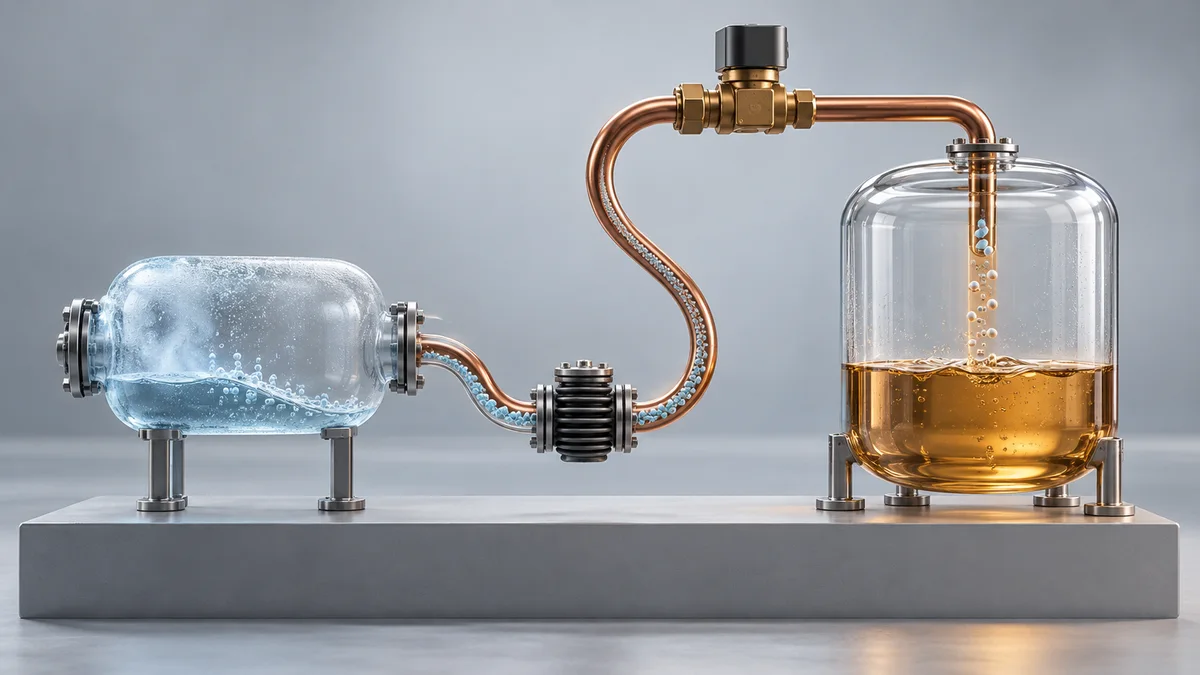
A cold-room pump-down sequence is a controlled shutdown method, not a service evacuation procedure. When cooling demand ends, the liquid-line solenoid valve closes first. The compressor continues running until the low-side pressure reaches the approved pump-down cut-out, then the low-pressure control stops it. On the next demand, the liquid valve opens, suction pressure rises, and the compressor is allowed to restart.
That simple description hides several design decisions: which device owns the cooling request, whether the pressure device is a control or a safety, how refrigerant leakage is handled, what happens during defrost, and how short cycling is prevented. This guide turns those decisions into a sequence and commissioning checklist. It does not provide a universal pressure setting; the compressor, refrigerant, equipment design, operating envelope, and manufacturer instructions must determine that value.
For related logic, see compressor anti-short-cycle delay and cold-room defrost scheduling. If the control hardware is still being specified, use the OEM controller I/O specification guide to define every signal and load.
What pump-down is meant to achieve
During a long off cycle, refrigerant can migrate toward a colder compressor and dissolve in the oil. Copeland's official Refrigeration System Design manual describes pump-down as closing a liquid-line solenoid valve, moving refrigerant toward the condenser and receiver, and stopping the compressor with a low-pressure control. The objective is to reduce refrigerant left on the low side and limit off-cycle migration.
Danfoss gives the same basic sequence in its compressor system-design guidance: close the liquid-line solenoid as the system reaches setpoint, let the compressor move most of the refrigerant to the high side, and stop on the pump-down pressure control. Both sources also make clear that the design remains application-specific. Receiver capacity, compressor operating limits, pressure-control settings, and the behavior of the selected valve all need to be checked for the actual system.
Pump-down does not replace high- or low-pressure safety protection, motor protection, approved compressor operating limits, a correctly selected receiver, a crankcase heater where required, or control of liquid floodback during operation. Treat it as one layer within the refrigeration design.
Define the normal stop and restart sequence
A functional specification should describe states and transitions rather than only listing outputs.
| State | Liquid-line solenoid | Compressor command | Expected evidence |
|---|---|---|---|
| Cooling | Open | Permitted subject to safeties | Room control calls for cooling; suction pressure is within the approved operating region |
| Pump-down | Closed | Continues temporarily | Cooling demand has ended; low-side pressure falls toward the approved cut-out |
| Pumped down | Closed | Off | Pressure control has opened and the compressor remains off |
| Restart | Opens first | Starts only after permissives | Suction pressure recovers; restart and anti-short-cycle conditions are satisfied |
| Fault or inhibited | Defined safe state | Off or controlled by the approved safety design | Alarm, reason, timestamp, and recovery action are available where the system supports records |
The restart transition deserves as much attention as shutdown. Opening the valve and energizing the compressor at the same instant can defeat the intended pressure-controlled sequence. Conversely, an excessive or unexplained restart delay can allow room temperature to drift. Specify the event that releases the compressor, every required permissive, and which protection has final authority.
Keep control and safety functions separate
A low-pressure device can be used as an operating control in a pump-down sequence, but a refrigeration design may also require an independent low-pressure safety function. Do not assume one contact, one software input, or one threshold automatically satisfies both jobs.
For each pressure device or transducer, document:
- whether it is a normal control, a safety, or a monitored indication;
- its physical connection point and isolation arrangements;
- cut-out, cut-in, differential, and any time qualification;
- manual or automatic reset behavior;
- electrical state for normal, tripped, broken-wire, and power-loss conditions;
- whether firmware can override it;
- how the operator distinguishes a normal pumped-down stop from a loss-of-charge or low-suction fault.
The pressure settings must come from the approved equipment and compressor documentation. Copeland's model-specific application guidelines require pump-down to stay inside the compressor operating envelope. A pressure switch should never be bridged to force the system lower, and a refrigeration compressor must not be used as a vacuum pump.
Specify the liquid-line solenoid as a pressure component
The valve is not just a binary output on an I/O list. It must close tightly enough for the intended sequence, open against the available pressure differential, suit the refrigerant and line conditions, and fail in the approved direction.
Danfoss's official solenoid-valve technical article explains that a valve in a pumped-down system can face the full differential between the high- and low-pressure sides while closed. Its maximum operating pressure differential depends on the selected valve and coil combination. Check the current manufacturer data rather than assuming that a coil voltage or pipe size proves the valve can reopen.
The project specification should capture:
- valve model, refrigerant compatibility, flow direction, connection size, and required approvals;
- maximum and minimum differential conditions for opening and closing;
- coil voltage, frequency or DC supply, inrush and holding load, and surge suppression;
- allowable seat leakage and how leakage is detected in operation;
- de-energized state and response to controller or power failure;
- service access, manual stem restrictions, and replacement identification.
If the valve leaks, low-side pressure may rise after the compressor stops. Depending on the approved design, that can trigger another short pump-down cycle or require a one-shot circuit that prevents automatic recycling. The correct choice is compressor- and system-specific; it should be documented and tested, not improvised in software after commissioning.
Coordinate pump-down with short-cycle protection
Pump-down pressure control and anti-short-cycle timing solve different problems. The pressure control ends or releases a sequence based on suction pressure. The anti-short-cycle function limits an unacceptable restart pattern. Both may be active at the same transition.
Write an explicit priority table for at least these cases:
- Cooling demand returns immediately after pump-down starts.
- The solenoid leaks and suction pressure rises while room demand remains satisfied.
- A brief power interruption occurs during pump-down.
- The pressure input becomes open, shorted, implausible, or unavailable.
- A manual cooling command is issued while a restart delay is active.
- The compressor contactor is commanded but current or auxiliary feedback does not confirm operation.
Do not allow a normal pump-down pressure transition to be reported as a refrigeration fault, but do not suppress a genuine low-pressure safety event merely because the controller believes it is in pump-down. Separate state, timer, pressure, and feedback evidence in the event record.
Decide how defrost changes the sequence
Defrost may require the refrigeration feed to stop before heaters or hot gas are enabled, and the restart may include drip-off, refrigeration recovery, and fan delay. The exact sequence depends on the defrost method and equipment design.
Define these questions for the selected system:
- Does a defrost request initiate pump-down, or may defrost start only after a separate pumped-down confirmation?
- What is the maximum allowed time to reach the pressure cut-out before declaring a fault?
- Which safeties remain active while defrost outputs are energized?
- Can a pump-down or pressure fault inhibit defrost, and what protects the evaporator if it does?
- After defrost, when does the liquid valve open, when may the compressor start, and when are fans released?
- How are simultaneous cooling, defrost, manual, and remote requests prioritized?
Do not copy this sequence from a different room simply because both systems use electric defrost. Receiver volume, valve behavior, evaporator arrangement, compressor limits, and defrost hardware can all differ.
Build a commissioning test around observable evidence
Commissioning should be performed by qualified refrigeration and electrical personnel using the equipment manufacturer's procedures. Do not bypass pressure, overload, phase, motor, or refrigerant-safety devices to create a test condition.
- Record the approved refrigerant circuit, charge, receiver, compressor documentation, valve data, pressure devices, electrical diagram, controller firmware, and parameter backup.
- Confirm output states with power isolated, then verify valve and contactor wiring, feedback polarity, and fail-safe behavior.
- Run at a representative load and record room temperature, suction pressure, valve command, compressor command, compressor feedback, and safety states.
- Satisfy the cooling request normally. Verify that the valve closes first, the compressor continues only through the approved pump-down interval, and the correct pressure device stops it.
- Hold the system off long enough to observe pressure rise. Record whether the design remains stopped, performs an approved recycle, or reports excessive leakage.
- Restore cooling demand. Verify valve opening, pressure recovery, safety permissives, anti-short-cycle behavior, and confirmed compressor start.
- Test defrost entry and exit through the approved operating procedure, including maximum pump-down time, drip-off, compressor restart, fan release, and alarm handling.
- Test an approved power-loss and restoration scenario. Confirm retained state, restart priority, and whether an unexpected cooling call can occur.
- Simulate only the faults permitted by the manufacturer: unavailable pressure input, missing valve feedback if fitted, failed compressor confirmation, and communication loss.
- Approve the sequence only when the trend, physical system response, alarms, and recovery actions agree with the specification.
Diagnose symptoms by sequence position
| Symptom | Evidence to inspect before changing settings |
|---|---|
| Compressor never stops after the valve closes | Valve flow direction and closure, wiring, pressure-control connection, refrigerant path, receiver capacity, pressure reading, and compressor operating limit |
| Compressor restarts repeatedly while demand is off | Valve seat leakage, pressure equalization, pressure-switch differential, recycling design, check-valve behavior, and anti-short-cycle logic |
| Cooling demand returns but the compressor does not start | Valve command and differential capability, suction-pressure recovery, safety chain, restart delay, power state, and contactor feedback |
| Low-pressure alarm appears on every normal stop | Separation of pump-down control from safety logic, state qualification, alarm delay, and event naming |
| Fault appears only after defrost | Defrost feed isolation, liquid accumulation, termination, drip-off, restart order, fan release, and pressure transients |
Changing the cut-out is not the first response to these symptoms. Collect the sequence evidence first, then compare it with the valve, compressor, receiver, and equipment documentation.
Applying the sequence to a Beamform controller project
The published standard functions of the BF-6800 / 6810 refrigeration controller include compressor control, startup delay protection, periodic defrost, fan management, alarms, and a configurable AUX output. The BF-6950 split-type refrigeration controller publishes compressor, defrost, fan, alarm, and current-detection functions. These pages do not publish a complete pump-down sequence, pressure input, liquid-line solenoid mapping, or the safety architecture described in this article as standard configuration.
For a standard product, confirm the exact model, firmware, terminals, parameters, and supported sequence before specifying it. Optional connectivity listed on the relevant product page should also be confirmed for the selected model. For an OEM/ODM project, pressure sensing, valve output, state logic, restart priorities, defrost integration, alarms, event records, HMI wording, and communication fields can be evaluated after the requirements are frozen.
Final feasibility, hardware, cost, MOQ, certification work, validation scope, and schedule depend on the confirmed project. Contact Beamform with the refrigerant circuit, compressor and valve documentation, electrical diagram, I/O list, power supply, contactor details, defrost method, pressure ranges, target market, certification requirements, expected quantity, and proposed acceptance tests.
Frequently asked questions
Is pump-down the same as compressor anti-short-cycle delay?
No. Pump-down moves refrigerant off the low side and stops the compressor on an approved pressure condition. Anti-short-cycle delay limits restart timing. A system may need both, with a documented priority when pressure and timer conditions overlap.
What pressure should a cold-room pump-down stop at?
There is no universal value. Use the current compressor and equipment documentation for the exact model, refrigerant, operating envelope, pressure device, and ambient conditions. Do not infer the setting from another installation.
Why does the compressor restart when the thermostat is satisfied?
One possible cause is refrigerant leaking through the closed liquid-line solenoid, which raises suction pressure until the pump-down control closes again. Check the approved recycling or one-shot design, valve leakage, pressure differential, check-valve behavior, and restart protection before changing a threshold.
Can one low-pressure switch provide pump-down control and safety protection?
Do not assume so. The functions can require different settings, reset behavior, wiring, independence, and fault response. The equipment risk assessment and applicable manufacturer instructions must define the architecture.
What project inputs are needed for a custom pump-down controller?
Provide the refrigerant schematic, compressor and receiver data, liquid-valve data, pressure ranges and devices, electrical diagram, I/O list, power and contactor details, normal/defrost/service state sequence, fault policy, HMI and protocol requirements, target market, certification needs, expected quantity, and acceptance tests.