
OEM Temperature Controller I/O Specification: Define Loads Before Hardware
Build an OEM temperature controller I/O specification for power, sensors, relays, contactors, fault states, protection, and acceptance testing.
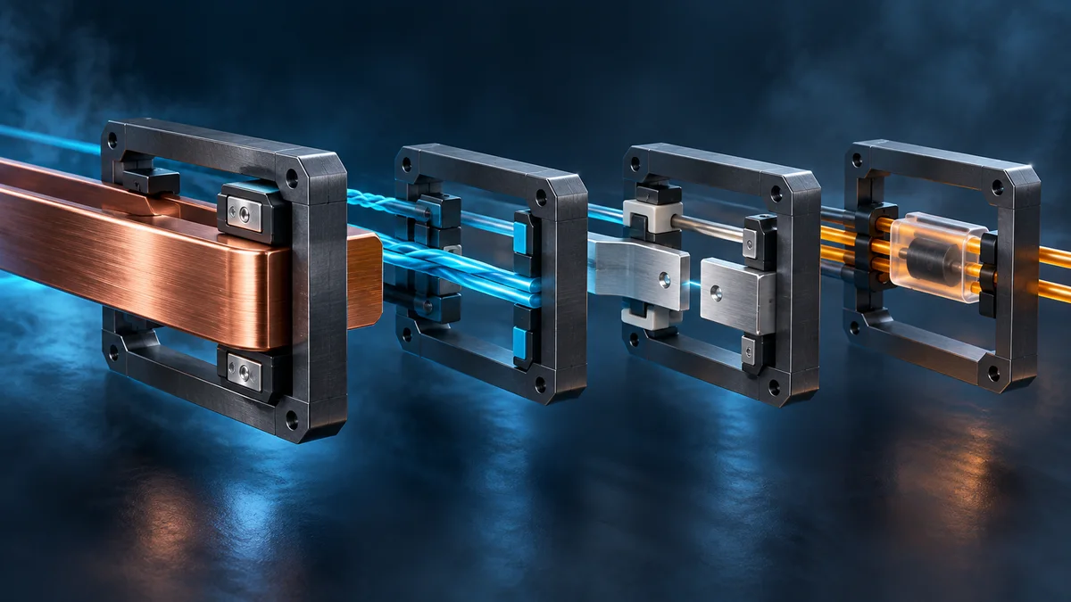
An OEM temperature controller I/O specification should define the electrical job before it names the hardware. “Three relay outputs” is not enough. Engineering still needs to know what each output controls, the load voltage and type, steady and starting behavior, switching frequency, external contactor arrangement, fault state, protection, and how the interface will be accepted.
This guide turns those unknowns into a buyer-ready specification. It complements the broader OEM temperature controller RFQ checklist by going deeper on power, sensor inputs, digital inputs, relay outputs, and their verification.
Why a current rating is not a load specification
A printed contact rating describes defined test conditions; it does not prove suitability for every load drawing the same steady current. Motors, solenoids, contactor coils, transformers, lamps, heaters, and capacitive power supplies behave differently when switched.
OMRON’s official relay guidance distinguishes resistive, inductive, lamp, and capacitive loads and shows that several categories can draw starting current well above their steady-state value. Panasonic likewise instructs designers to consider load type, inrush, switching frequency, ambient conditions, and real-machine verification rather than relying on one current value (OMRON load guidance; Panasonic relay precautions).
The procurement consequence is simple: specify the actual electrical interface, not only the nominal current from a load nameplate.
Build one controlled row for every connection
Create an I/O matrix and give every terminal or connector position a stable identifier. A useful row contains:
| Field | What the buyer should provide |
|---|---|
| Function | Compressor command, defrost heater, fan, alarm, sensor, door input, or another named job |
| Electrical type | Supply input, NTC/PTC/analog input, dry or powered digital input, relay contact, transistor output, or communication port |
| Normal values | Nominal and allowed voltage/frequency, sensor curve, signal range, polarity, and reference |
| Connected device | Exact load or external interface, including manufacturer part number when available |
| Load profile | AC or DC, resistive/inductive/capacitive, steady current, measured or declared inrush, power factor or coil data, and switching rate |
| Wiring | Terminal assignment, wire size, cable length, shielding, connector, earthing, and separation assumptions |
| State behavior | Power-up, normal control, standby, sensor fault, communication loss, reset, and de-energized state |
| Protection | Upstream overcurrent protection, interlock, suppression, isolation, and protection owned by the finished equipment |
| Acceptance | Inspection or test that proves the requirement, with limits and evidence to retain |
Link each row to the electrical drawing and control sequence. If one output changes function by parameter, list every permitted assignment and prevent combinations that would create an unsafe or undefined state.
Specify the power input as an operating envelope
“230 V” or “24 V” alone does not define a power input. Record:
- nominal voltage, allowed steady range, frequency where applicable, and supply type;
- connector and terminal arrangement, protective earth or other reference, and polarity for DC;
- behavior during startup, brownout, brief interruption, restoration, and repeated cycling;
- maximum expected load on auxiliary supplies, sensors, displays, and communication modules;
- installation category, enclosure, pollution, temperature, condensation, and other environmental assumptions that the applicable design review needs;
- upstream disconnect, overcurrent protection, and which protective functions remain outside the controller.
IEC 60730-2-9:2026 covers construction, operation, and testing of temperature-sensing controls within its stated scope, including operating values, times, sequences, and performance where these affect equipment safety. Citing the standard in an RFQ does not establish compliance. The buyer must still identify the finished equipment, target market, applicable standards, mounting method, ratings, and conformity owner.
Define sensor and digital inputs beyond the signal name
For every temperature or humidity input, provide the sensor technology and characteristic, measurement range, control range, cable length, connector, mounting, environment, and required response. For a thermistor, naming only “NTC” leaves the nominal resistance, beta value or curve, tolerance, and fault thresholds unresolved.
For a digital input, state whether it expects a dry contact or a powered signal, its normal and active states, wetting or test requirements where relevant, cable routing, debounce or persistence behavior, and the response to open circuit, short circuit, and invalid combinations. A door switch, pressure switch, remote enable, and alarm reset may all be “digital inputs,” but they do not have the same safety meaning or failure response.
Then define what the firmware does with each fault: alarm only, inhibit an output, enter an agreed fallback, latch until service, or recover automatically after a valid signal persists. The prototype validation plan can turn these states into traceable tests.
Separate the control command from the switched load
For each output, first decide whether the controller switches the final load or only commands an external relay, contactor, solid-state device, or drive. A compressor symbol on the display does not prove that the onboard contact is intended to switch a compressor motor directly.
Ask for the connected-device data sheet and record:
- load and control-circuit voltage, AC or DC;
- steady current plus starting, locked-rotor, magnetizing, or capacitive inrush where applicable;
- make and break duty, power factor or time constant where relevant;
- expected operations per hour and operating pattern;
- minimum load if a mechanical contact must switch a very small signal;
- external contactor, interposing relay, SSR, fuse, breaker, overload, and interlock arrangement;
- required normally open or normally closed behavior and the de-energized safe state.
OMRON notes that transformers, motors, and lamps can create large inrush and contact welding, while inductive loads can create reverse voltage at turn-off. Panasonic similarly requires checking the real load and operating conditions. These are selection inputs, not universal multipliers to copy into a purchase specification.
Treat coil suppression as part of the interface
An external contactor coil is an inductive load. Schneider Electric explains that opening a contactor coil can generate a high surge and that its TeSys coil suppressor modules are intended to limit that voltage (Schneider Electric technical FAQ).
Do not add an arbitrary suppressor after the controller is released. Record the coil part number, voltage, built-in suppression, supplier-approved external suppression, wiring location, and any effect on release time. Then test the complete controller-output/coil/suppressor combination under the approved supply and temperature conditions. Protection for one coil family may not be the right design for another.
Decide whether the project is standard, optional, or custom
Use three explicit disposition labels during supplier review:
- Standard configuration: the selected published model, terminal arrangement, sensor, supply, and output interface meet the documented requirement without a product change.
- Optional configuration: a documented option exists, but its compatibility, part number, wiring, firmware, price, and availability still need confirmation for the project.
- Project-evaluated customization: a different relay, power supply, sensor interface, terminal layout, PCB, isolation scheme, firmware behavior, or protection architecture requires engineering review and validation.
Do not let “customizable” become an assumed approval. The disposition should identify the responsible owner, evidence required, and change baseline. Mechanical clearances and terminal access should also remain aligned with the enclosure and panel-interface specification.
Use an acceptance plan that exercises the real interface
A useful acceptance plan is proportional to risk and the agreed design. It may include:
- Inspect the released schematic, I/O matrix, bill of materials, terminal labels, and wiring sample for consistency.
- Verify every input at its agreed normal, boundary, open-circuit, short-circuit, and recovery conditions where those tests are applicable and safe.
- Operate every output with the approved representative load or qualified simulator, including the specified starting behavior and switching pattern.
- Check power-up, interruption, restoration, reset, sensor fault, communication loss, and interlock priorities.
- Confirm that external contactors, overloads, suppressors, and protective devices are present and wired as released.
- Review temperature rise, contact behavior, noise effects, and enclosure conditions using the methods and limits agreed by the responsible engineers.
- Retain the configuration, equipment identity, measured results, deviations, approvals, and final wiring evidence.
A bench lamp or resistance box does not automatically represent a compressor contactor, solenoid valve, heater, or electronic power supply. The acceptance record should state what was actually connected and which claim the test supports. For production release, connect this plan to the OEM controller production quality plan.
Apply the framework to a Beamform project
Beamform’s published BF-6800 / 6810 product page lists an AC220V supply, NTC 5K B3470 sensor, 5A/250V contact capacity, and model-specific refrigeration functions as the standard platform information. The BF-6812LC page also lists AC220V, NTC 5K B3470, and a 5A/250V output, while describing a larger relay as customization rather than standard equipment.
Those published values are a starting point, not approval for an unspecified load. Confirm the exact model, terminal diagram, output assignment, connected devices, inrush and switching duty, external protection, environment, and acceptance method. Alternative supplies, sensors, relays, terminal layouts, PCBs, firmware states, communication, and protection features are evaluated against the project specification.
Final feasibility, component choice, test scope, certification work, cost, MOQ, tooling, and schedule can only be confirmed after the electrical package and expected quantities are reviewed. Contact Beamform with the application environment, power diagram, I/O matrix, load data sheets, panel dimensions, target markets, certification requirements, prototype and production quantities, and proposed acceptance plan.
Frequently asked questions
Is a 5 A relay suitable for a 3 A compressor or fan?
Not from those two numbers alone. The answer depends on voltage, load type, starting and breaking behavior, switching frequency, contact rating conditions, environment, protection, and whether the controller drives the final load or an external contactor. Review the actual circuit and validate it with the approved load.
Should a temperature controller switch the compressor directly?
Do not assume so. The equipment designer should decide whether the controller output operates the compressor circuit directly or commands an external contactor or other device, based on the documented ratings, load behavior, protection, and applicable equipment requirements.
What is the minimum I/O information needed for a quotation?
Provide the supply envelope, one row per input and output, connected-device data, load voltage/type/steady and inrush behavior, switching rate, fault states, wiring diagram, protection concept, target market, expected quantities, and acceptance method. Mark unresolved values as open items rather than guesses.
Can the supplier choose the relay from the load wattage?
Wattage alone is insufficient. AC/DC type, current waveform, inrush, break duty, power factor or time constant, switching frequency, ambient conditions, minimum load, and protection can all affect selection.
When does an I/O change become a new validation baseline?
When it can change electrical behavior, safety assumptions, firmware states, wiring, thermal performance, EMC behavior, or compatibility. Record the impact assessment and required regression tests before approving the change for samples or production.
Sources
- IEC 60730-2-9:2026 — Particular requirements for temperature sensing controls
- OMRON — General Purpose Relays: load types and inrush current
- OMRON — General Purpose Relays: load conditions and contacts
- Panasonic Industry — Relays: cautions for use
- Schneider Electric — Surge suppressor modules for TeSys contactor coils