
OEM Temperature Controller Enclosure: Specify the Mechanical Interface
Define an OEM temperature controller enclosure with clear panel cutouts, mounting, sealing, wiring clearance, artwork, DFM, and verification inputs.
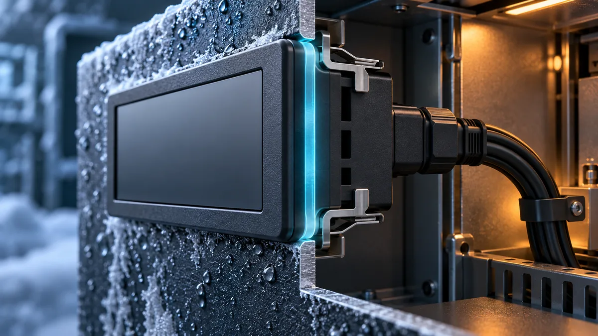
An OEM temperature controller enclosure specification should do more than show an attractive front panel. It must define how the controller fits the host equipment, seals at the mounting boundary, connects to wiring, leaves room for service, and remains identifiable through future revisions.
That work starts before anyone discusses a new mould. A standard housing may already fit. A custom overlay may solve the brand requirement. A new bezel, rear housing, bracket, gasket, or complete enclosure may be justified only when the mechanical and environmental requirements demand it.
This guide gives procurement and engineering teams a decision framework and a practical input package. It does not assume that a custom enclosure, ingress rating, material, tooling process, certification, cost, minimum order quantity, or schedule is included in a standard controller or quotation.
Decide which mechanical layer actually needs to change
Treat “custom enclosure” as several possible scopes rather than one feature.
| Scope to evaluate | What stays fixed | What may change | Evidence to request |
|---|---|---|---|
| Standard housing | Existing bezel, rear body, mounting method, and cutout | Artwork, approved label, parameter defaults, or packaging | Artwork proof, label specification, approved sample |
| Standard platform with mechanical adaptation | Some existing housing or electronics | Overlay, bezel, bracket, gasket, connector position, or mounting hardware | Interface drawing, fit sample, sealing and service-access checks |
| New enclosure | Only approved electrical and functional requirements | Housing geometry, material, texture, mounting, sealing, and internal supports | Released CAD, DFM review, tooling plan, dimensional report, validation results |
These are planning routes, not promises about what a supplier can deliver. Ask the supplier to classify each requested change as standard, optional on an existing platform, or project-evaluated customization before comparing quotations.
If the controller can use an existing housing, validate the application before redesigning it. If it cannot, document the constraint that forces the change: panel opening, viewing area, cabinet depth, connector access, washdown exposure, cleaning chemistry, mounting orientation, brand geometry, or another measurable requirement.
Define the host-equipment boundary first
A controller drawing cannot be approved in isolation. Provide the mechanical context around it:
- Panel material, thickness, flatness, and any coating or insulation.
- Cutout dimensions, corner radii, tolerances, burr limits, and datum scheme.
- Maximum front, rear, and side envelope in every permitted orientation.
- Door swing, nearby hinges, cable duct, contactors, terminals, and other collision zones.
- Mounting direction, retaining method, installation access, and tool access.
- Required display viewing area, button or touchscreen reach, and glove use.
- Cable entry direction, mating-connector envelope, strain relief, and service loop.
- External and internal exposure: condensation, frost, dust, dripping water, cleaning, UV, oil, salt, impact, and vibration.
Photographs are useful, but they do not replace a controlled drawing or 3D assembly. Include the panel and surrounding keep-out volumes in the CAD package so a fit problem is found digitally rather than after a mould or production panel exists.
For a broader electrical and functional input list, use the OEM temperature controller RFQ checklist alongside this mechanical package.
Treat ingress protection as an assembly requirement
IEC 60529 classifies the degrees of protection provided by electrical-equipment enclosures using the IP Code. That classification is not created by selecting a gasket from a catalogue or by describing a front panel as “waterproof.” The defined enclosure, mounting surface, joints, openings, accessories, and test configuration have to work together.
UL makes the same system-level point from another direction: its guidance for environmental-rated enclosure accessories covers items such as windows, plugs, cable seals, handles, hinges, latches, and gaskets because a panel-mounted component can affect whether the assembled product maintains its environmental seal.
Write the requirement in testable terms:
- Which boundary is being rated: the controller front after panel mounting, the complete controller, or the host enclosure?
- What panel material, thickness, surface finish, cutout, fastener torque, and gasket are part of the tested assembly?
- Which cable entries, connectors, vents, covers, and unused openings are present?
- What installation orientation and exposure represent actual use?
- Which standard, edition, test laboratory, report, and marking are required for the target market?
Do not translate an IP target into a NEMA Type by resemblance. The ANSI overview of ANSI/NEMA 250-2020 describes a Type system with construction, application, marking, and design-test requirements for specific environmental conditions. Schneider Electric’s 2025 equipment-enclosure rating bulletin compares IEC 60529, NEMA, and UL systems precisely because their scopes and rating structures differ. State the target system explicitly and have the applicable requirements reviewed for the finished product.
Separate the front-face seal from the full controller
For a panel-mounted controller, the exposed front and the rear electronics can live in very different environments. The front may face a cold room or cleaning process while the rear sits inside a protected cabinet. This leads to three separate questions:
- Is the bezel-to-panel joint sealed after installation?
- Are display windows, buttons, touch layers, seams, and overlays part of that boundary?
- Does the claim apply only to the installed front face, or to the complete controller including rear connectors and housing joints?
Record the answer on the drawing and in the test plan. A front-face result should not be broadened into a whole-product claim, and a component rating should not be used as evidence for an untested assembly.
Reserve wiring and service clearance
The rear envelope should include the space needed to install and maintain the controller, not only the plastic body. Model and dimension:
- Mating connectors, terminal covers, ferrules, and the direction of screwdriver access.
- Cable bend and pull-out space based on the selected cable and connector supplier’s requirements.
- Strain relief, shielding termination, earth connection, and separation required by the electrical design.
- Retaining clips or brackets through their full installation and removal path.
- Access needed to identify terminals, read labels, replace a fuse if applicable, or disconnect the unit without dismantling unrelated equipment.
A connector that fits in CAD but cannot be reached after the cabinet is wired is not a usable interface. Ask the prototype review to include an installation by the people who will actually assemble or service the equipment.
Define materials from the real environment
“ABS enclosure” or “metal panel” is not a complete material requirement. State the expected temperature and humidity range, condensation or frost, UV exposure, cleaning agents, oils, salt, impact risk, flammability requirement, colour, texture, and acceptable cosmetic change over life. The applicable equipment and market requirements must determine the final material and verification plan.
If a new moulded housing is being evaluated, request a DFM review before design release. Protolabs’ injection-moulding design guidance explains why draft, wall thickness, ribs, radii, core/cavity strategy, undercuts, gates, and ejection all interact with mouldability and appearance. Do not copy a universal wall thickness or draft angle into the specification; ask the moulder to evaluate the selected resin, finish, geometry, tooling process, and tolerance stack together.
Control the visible interface and artwork
The enclosure is also an operator interface. Release the visible elements with the same discipline as the mechanical parts:
- Display active area, viewing direction, contrast target, and any protective window.
- Button, encoder, or touchscreen location and usable target size.
- Overlay construction, adhesive system, print layers, texture, colour references, and cleaning exposure.
- Exact logo, model, rating, terminal, warning, and traceability artwork supplied as controlled files.
- Required language variants and the rule for matching artwork to firmware and documentation.
- Cosmetic zones, colour tolerance method, permitted gate/ejector evidence, and defect limits.
Do not add certification marks to concept artwork. Markings should be released only after the applicable product, market, authorization, and production-control requirements have been confirmed.
Release a mechanical interface package
Before tooling or a production sample, the buyer and supplier should agree one controlled package containing:
- A 2D interface drawing with datums, critical dimensions, tolerances, panel cutout, panel thickness range, and keep-out zones.
- A 3D assembly model showing the host panel, controller, retainers, connectors, and cable space.
- Part drawings for the bezel, housing, bracket, gasket, overlay, lens, and inserts that are in scope.
- Material, colour, finish, texture, and cosmetic specifications.
- An environmental and ingress requirement that identifies the rated boundary and test configuration.
- Artwork, label, terminal identification, and serialization requirements.
- A critical-characteristic list and the proposed inspection method.
- Revision identifiers and an approval record linking CAD, drawings, samples, and test evidence.
That package should feed the prototype validation plan, then become part of the controlled production baseline described in the OEM production quality plan.
Verify the installed interface, not only loose parts
Verification should use representative panel material, thickness, finish, cutout, fasteners, gasket, connectors, and cable routing. Depending on the agreed requirements, the evidence may include:
- Dimensional inspection and tolerance-stack review.
- Installation, removal, connector-access, and tool-access trials.
- Repeated assembly checks for clips, threads, gasket compression, and overlay edges.
- Display visibility and operator-use checks in the intended orientation.
- Environmental, ingress, cleaning, impact, vibration, or transport tests required by the application.
- Inspection after testing for water paths, cracking, distortion, loose hardware, label damage, and loss of function.
The current IEC 60730-2-9:2026 covers construction, operation, and testing of temperature-sensing controls within its scope. It also notes that a control response affected by how the control is mounted must be addressed by the relevant equipment requirement or manufacturer definition. That is another reason to validate the controller in its intended mounting condition rather than relying only on a loose bench sample.
Beamform standard products and project-evaluated changes
Beamform’s published product pages provide concrete starting references, not universal mechanical promises:
- The BF-6800 / 6810 standard product page specifies a 92 × 42 mm panel cutout and AC 220 V supply for that platform.
- The split BF-6910 / 6911 page specifies a 193 × 133 mm touchscreen panel, a 187 × 126 mm cutout, an AC 220 V mainboard, and DC 12 V to the screen.
Those are published standard configurations for the named models. A different cutout, bezel, housing, gasket, mounting method, material, connector layout, supply arrangement, ingress claim, artwork, or certification scope must be evaluated against the project specification. Feasibility, cost, minimum order quantity, tooling, test scope, and schedule can be confirmed only after the mechanical, electrical, environmental, target-market, and volume inputs are reviewed.
To request that review, contact Beamform with the interface package rather than only a reference photo.
Buyer handoff checklist
Before requesting an enclosure quotation, send:
- Host-equipment 2D drawing and 3D assembly.
- Panel material, finish, thickness range, cutout, tolerances, and datums.
- Front, rear, side, connector, cable, clip, and tool-access envelopes.
- Installation orientation and assembly/service sequence.
- Temperature, humidity, condensation, frost, UV, cleaning, chemical, impact, and vibration exposures.
- Required IP or NEMA system, rated boundary, test configuration, target market, and applicable standards.
- Display, input-device, artwork, language, label, and traceability files.
- Electrical diagram, connector list, harness details, and cable requirements.
- Prototype quantity, expected production quantity, and planned product variants.
- Acceptance tests, document deliverables, approval owners, and revision process.
Frequently asked questions
Can I design the equipment around a 92 × 42 mm cutout?
That is the published cutout for Beamform’s BF-6800 / 6810 platform, but fit also depends on panel thickness, tolerances, rear clearance, retaining access, connectors, wiring, orientation, and the electrical application. Validate the complete assembly before releasing the host panel.
Does an IP-rated front mean the complete controller has the same rating?
Not automatically. The rated boundary and test assembly must be stated. The front joint, panel, gasket, openings, rear housing, connectors, and accessories can define different boundaries.
When should an OEM buyer consider a new enclosure?
Consider it when measurable requirements cannot be met with a standard housing or a limited adaptation. Freeze the interface and environmental requirements first, then compare the verified scope of each route. Do not use appearance alone to trigger tooling.
What is the minimum information needed for an enclosure review?
Provide the panel and surrounding CAD, cutout and tolerance drawing, mounting and service sequence, wiring envelope, environmental exposure, target market and standards, artwork, expected quantities, and acceptance evidence. The supplier can then identify which elements are standard, optional, or project-evaluated.
Sources
- IEC 60529 — Degrees of protection provided by enclosures (IP Code)
- IEC 60730-2-9:2026 — Particular requirements for temperature sensing controls
- ANSI — Enclosures for Electrical Equipment, ANSI/NEMA 250-2020
- Schneider Electric — IEC 60529, NEMA 250, and UL 50 Compared
- UL Solutions — Environmental-Rated Accessories for Enclosures
- Protolabs — Design Essentials for Injection Moulding