
Cold Room Temperature Probe Fault Diagnosis: Open, Short or Drift?
Diagnose cold-room temperature probe faults systematically: separate open circuits, shorts, drift, wiring noise and placement errors before changing controller settings.
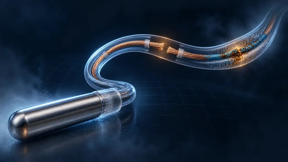
A cold-room temperature probe fault does not always look like a fault. A broken conductor may produce an immediate sensor alarm, but the more difficult cases show a believable temperature that is simply wrong, changes when a cable moves, or disagrees with the actual product and room conditions.
Replacing the controller first is rarely a useful diagnostic method. A better process separates the probe element, field cable, terminals, controller input, configuration, and physical mounting. This guide gives refrigeration technicians and equipment builders a repeatable way to do that without hiding the problem with an offset or an alarm-delay change.
If the electrical reading is healthy but the measurement does not represent the room, use our cold-storage temperature sensor placement guide. For faults that appear only around defrost, also review defrost termination temperature and probe placement.
Start with how an NTC input measures temperature
An NTC thermistor is a temperature-dependent resistor: its resistance decreases as temperature rises. The relationship is nonlinear, so the controller must use the correct resistance-versus-temperature curve, not only a nominal resistance printed at one reference temperature. TDK's NTC technical information explains the exponential behavior and why tabulated R/T curves or suitable conversion models are needed over a useful range.
This means a complete measurement channel includes more than the metal probe tip. It includes:
- the thermistor element and its specified R/T curve;
- encapsulation, cable, joints, connector, and terminals;
- the controller's excitation, bias components, analog input, and conversion algorithm;
- the configured sensor type, correction, filtering, and fault limits;
- the physical location and thermal contact between the probe and what it is meant to measure.
TDK's digital-readout application note treats sensor tolerance, bias-resistor tolerance, supply variation, ADC error, and noise as contributors to measurement uncertainty. A displayed temperature is therefore the result of a chain, not proof that the probe alone is correct.
Four fault patterns that require different tests
1. A hard open or short circuit
An open circuit is a broken current path: a snapped conductor, loose terminal, disconnected plug, or failed internal connection can all cause it. A short circuit creates an abnormally low-resistance path, potentially through crushed insulation, bridged terminals, water contamination, or conductor damage.
Many refrigeration controllers detect both conditions as an out-of-range sensor input. For example, the official Danfoss ERC 113C/D guide lists separate sensor-failure codes and describes each as a short or open circuit. Do not assume every controller uses the same code, detection threshold, delay, or output response; check the actual model manual.
2. A plausible but biased reading
A probe can remain inside the controller's valid electrical range and still report the wrong temperature. Common causes include the wrong NTC curve, an incorrect sensor-type setting, a poor splice, connection resistance, moisture ingress, a damaged element, or an unjustified calibration offset.
Two probes both described as “5 kΩ” are not automatically interchangeable. Rated resistance, reference temperature, B value, tolerance, operating range, encapsulation, and R/T table must match the controller requirement. A single room-temperature resistance check cannot validate the complete curve.
3. An intermittent or noisy reading
If the display jumps when a door moves, a fan starts, a contactor operates, or the cable is touched, inspect wiring and routing before changing control parameters. Loose terminals, damaged flex points, poorly protected splices, induced electrical noise, and condensation at a connector can create intermittent behavior.
For long sensor runs, TDK notes that shielded twisted-pair cable can reduce EMI-related errors. That does not make every extension acceptable: the controller and probe instructions still determine cable type, maximum length, shielding termination, joint method, and separation from power wiring.
4. A correct electrical reading from the wrong thermal location
A probe near a door, supply-air jet, defrost heater, warm wall penetration, or unrepresentative product stack may be electrically perfect and operationally misleading. A coil probe with poor surface contact can also lag or lead the temperature that should govern defrost.
Compare the suspect probe with a suitable independent reference at the same location and allow both to stabilize. Comparing instruments in different airflow or on different parts of a coil tests the installation, not just the sensors.
Use symptoms to choose the next check
| Symptom | More likely first checks | Do not conclude yet |
|---|---|---|
| Immediate probe-error code | terminals, connector, cable continuity, open/short state, correct input assignment | that the controller has failed |
| Fixed extreme or implausible value | open/short behavior, sensor type, input configuration, wiring | that the room actually reached that temperature |
| Stable but consistently biased value | probe curve, independent reference, splice resistance, moisture, mounting | that an offset is the correct repair |
| Reading jumps with equipment switching | cable route, terminals, shielding, grounding practice, input noise | that more software filtering solves the cause |
| Reading differs only during door opening or defrost | location, response time, thermal contact, control-state history | that the probe element is defective |
| Fault disappears when cable is moved | flex damage, loose joint, connector contamination | that the system is safe to return to service |
A step-by-step diagnostic workflow
1. Protect the load and record the state
Before disconnecting anything, apply the site's product-protection and equipment-safety procedure. Note the displayed value, alarm code, active outputs, operating state, recent defrost or door events, and when the symptom began. If the controller logs input values and alarms, preserve that evidence.
Do not force a compressor, heater, fan, valve, or contactor simply to clear a sensor alarm. The appropriate safe state depends on the application and must come from the equipment design, not a generic internet rule.
2. Identify the exact sensor requirement
Confirm the controller input, sensor role, nominal resistance, B value or R/T curve, allowable range, cable requirements, and configuration setting. Label room, evaporator, condenser, and auxiliary probes so one input is not diagnosed using another input's specification.
The standard published configuration for Beamform BF-6800/6810 and BF-6801/6811 models lists an NTC 5K B3470 sensor. That statement applies to those listed standard models; alternative sensor interfaces are not assumed stock features and must be evaluated for a defined project.
3. Compare at the measurement point
Use an appropriate reference instrument beside the installed probe. Allow for response time, airflow, surface contact, and thermal mass. If both instruments move together but the controller has a fixed bias, investigate the electrical chain and configuration. If they disagree only under certain operating states, inspect placement and contact.
4. Isolate probe, cable, and controller input
With power isolated and according to the equipment manual, inspect terminals, strain relief, crushed sections, sharp edges, wet joints, and connector pins. Qualified personnel can then test the disconnected probe circuit with a suitable meter and compare resistance with the manufacturer's R/T table at the independently measured temperature.
Test from more than one accessible point when the installation allows it. A correct value at the probe but not at the controller end points toward the field cable or a joint. A known-compatible test device at the controller input can help separate the input channel from the installed probe circuit, but only use methods and simulators approved for that controller.
5. Look for intermittency deliberately
Observe the measurement while gently checking approved cable flex points, connectors, and terminal stability. Repeat the observation through relevant equipment states such as compressor start, fan operation, defrost, and door movement. Do not disturb live hazardous wiring or bypass protection.
Moisture deserves special attention in cold rooms. TDK's sensor-sealing application note explains that moisture can migrate through material junctions toward the sensor head and stresses complete encapsulation and sealed cable construction for exposed sensors. Inspect not only the metal tip but also joints, cable entries, connectors, and places where condensation can collect.
6. Restore, verify, and document
After repair or replacement, verify the correct sensor type and input assignment, secure the cable, restore sealing, and observe the system through a representative control cycle. Confirm the displayed reading, output sequence, alarms, recovery, and any remote data point. Record the installed sensor specification, test result, repair location, and final comparison with the reference instrument.
Do not use calibration offset as a universal repair
An offset can compensate for a documented, stable measurement difference within the controller's permitted procedure. It cannot repair a loose terminal, wrong R/T curve, moisture path, damaged cable, intermittent connection, poor location, or failing input circuit.
Before applying correction, answer three questions:
- Is the difference stable across the required operating range?
- Was the comparison made at the same thermal point with a suitable reference?
- Is the root cause understood and the correction allowed by the equipment procedure?
If the bias changes with temperature, time, cable movement, defrost, or equipment switching, investigate the changing cause instead of adding a single number.
Define sensor-fault behavior before commissioning
Detecting a fault is only half of the control requirement. The equipment specification should define what happens next for each sensor role:
- which code, alarm relay, remote message, and event record are generated;
- whether outputs stop, continue, use a timed fallback, or use another validated input;
- which protections remain independent of the temperature controller;
- how a defrost or fan sequence behaves if its evaporator probe fails;
- what is required before automatic recovery is permitted;
- how service personnel distinguish an input fault from a high or low process temperature.
There is no universal safe fallback. A response suitable for a small refrigerated cabinet may be unsafe for a heater, large cold room, process skid, or system with hazardous product. The equipment designer must evaluate the load, independent protection, monitoring, and consequences of both continued operation and shutdown.
For OEM development, include open circuit, short circuit, out-of-range, intermittent, wrong-sensor, power-cycle, and recovery cases in the acceptance matrix. Our custom controller prototype validation plan shows how to connect those cases to requirements and objective evidence.
Beamform standard and project-evaluated options
Beamform's published BF-6800/6810 and BF-6801/6811 specifications identify NTC 5K B3470 sensors as standard configuration, alongside refrigeration, defrost, fan, and alarm functions described on their product pages. Confirm the selected model, probe quantity, wiring, and required behavior in the applicable product information.
Different sensor curves, additional inputs, connector or harness changes, custom fault thresholds, fallback sequences, HMI messages, logging, and communication data points are project-evaluated customization. Feasibility, validation, compliance work, cost, MOQ, and schedule are confirmed only after the application, electrical drawing, I/O list, sensor specification, environment, target market, and expected quantity are reviewed.
Browse the BF-6800 / 6810 refrigeration controller, compare the compact BF-6801 / 6811, or contact Beamform with the fault-response and sensor requirements for your equipment.
Frequently asked questions
How can I tell whether an NTC temperature probe is open or shorted?
Use the controller's documented fault code first, then isolate power and test the disconnected circuit using the equipment and probe instructions. An open circuit has a broken path; a short has an abnormally low-resistance path. The displayed temperature or code depends on the controller's input design, so do not infer the fault only from an extreme display value.
Can I replace an NTC probe with another probe of the same resistance?
Only if the complete specification matches the controller requirement, including the reference resistance, reference temperature, B value or R/T curve, tolerance, range, encapsulation, cable, and environmental suitability. Matching one nominal resistance is not enough.
Why does a probe fault appear only during defrost?
Heat, meltwater, condensation, cable movement, and output switching can expose a weak joint, moisture path, routing problem, or poor coil contact. Record the exact defrost state and compare probe behavior with heater, valve, compressor, and fan events before replacing parts.
Should the compressor keep running if the room probe fails?
There is no universal answer. The required fallback depends on the refrigeration system, load, independent protection, monitoring, and risk assessment. It must be defined and validated for the specific equipment rather than copied from another controller.