
Cold Storage Temperature Sensor Placement: A Practical Guide
Learn where to place cold-room temperature sensors, how to avoid misleading readings, and how to validate a monitoring layout before relying on it for alarms or records.
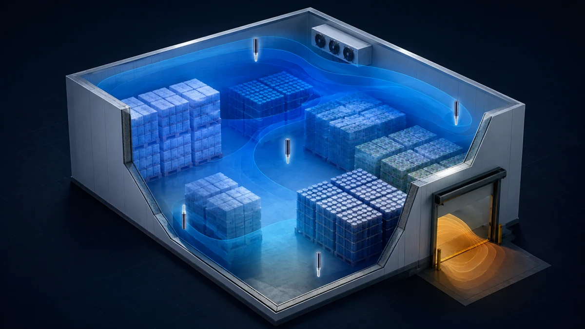
A temperature controller can only control what its sensor sees. Put a probe in the wrong place and the display may look stable while product in another part of the cold room is warmer, colder, or cycling through a larger range than expected.
That is why cold storage temperature sensor placement is a design decision, not a last-minute wiring detail. This guide explains how to position control and monitoring sensors so the readings represent the conditions that matter, then how to validate the layout before operators depend on alarms or records.
If you are choosing the controller itself, start with our cold storage thermostat selection guide. For installations that also need off-site alarm visibility and historical data, see our guide to remote cold-room monitoring.
Start with the purpose of each temperature reading
Do not assume every probe needs to sit in the same location. A cold room may use different readings for different jobs:
- Control sensor: drives the refrigeration control logic and should represent the room condition you want to maintain.
- Evaporator or coil sensor: supports defrost termination, fan delay, and other equipment logic; it is not a substitute for a room or product-temperature sensor.
- Alarm or monitoring sensor: checks the condition that could put stored goods at risk, which may be a different point from the control sensor.
- Product-simulation sensor: measures a buffered or representative product condition when a fast air-temperature response would be misleading for the operating objective.
Define the purpose before choosing the mounting point. A sensor installed to finish defrost should be close to the evaporator; a sensor intended to warn of warm product must not be tucked beside the coldest discharge air.
Avoid the locations that create misleading readings
Air in a cold room is not uniform. Fans move it, doors disturb it, product blocks it, and heat enters through surfaces and loading activity. These locations often create readings that are real but not representative:
- directly in the evaporator discharge stream, where air can be colder than the stored zone;
- immediately beside a return-air path, where readings may respond differently from the room average;
- next to doors, strip curtains, loading openings, or frequently opened access panels;
- against exterior walls, ceilings, or floors affected by heat transfer;
- behind stacked cartons or inside a stagnant pocket with little air circulation;
- near lights, heaters, motors, or other local heat sources.
Avoiding these spots does not mean ignoring them. A door area can be an excellent additional monitoring point if it is a known risk zone. The point is to avoid letting a local extreme become the only signal that controls the room.
Choose a representative control-sensor position
For a typical single-zone cold room, begin with a point in the occupied storage area where air can circulate around the probe but the probe is protected from direct fan discharge, door drafts, and physical damage. Mounting height should relate to the goods and the room's airflow pattern—not simply to the easiest cable route.
Walk the room before installation. Note the evaporator position, return path, door, shelving, pallet layout, and places where warm product is introduced. In a tall room, conditions can differ between low and high pallet positions; in a long room, the far end may respond differently from the end near the refrigeration equipment.
The best final location comes from observed conditions, not a universal distance rule. The refrigeration designer, installer, and food-safety or quality team should agree on what the control sensor is intended to represent.
Add sensors where the risk is different from the average
One well-placed sensor may be enough for basic control, but it is rarely enough to understand every storage zone. Consider additional monitoring points when the room has:
- a loading door or staging area with frequent warm-air infiltration;
- high racks, dense pallet storage, or blocked air paths;
- multiple evaporators or a long, irregular footprint;
- separate commodity zones with different temperature sensitivity;
- a history of complaints, excursions, frost, or uneven product condition.
These extra points do not have to control the compressor. They can provide alarms, trend data, or a comparison against the main control sensor. When readings begin to diverge, the difference itself is useful evidence: it can suggest airflow changes, loading practice, door use, or a sensor problem that deserves investigation.
Protect the probe without isolating it from the room
A probe needs mechanical protection, but an oversized enclosure or a tight wrap can slow its response and create its own measurement bias. Use a suitable mounting method and cable protection for the wash-down, condensation, impact, and cleaning conditions of the site. Keep the sensing element exposed to the intended air or product environment according to the sensor manufacturer's instructions.
Label each sensor in drawings and in the controller or monitoring system. A clear name such as “room control,” “door-side monitor,” or “high-rack monitor” prevents a service visit from turning into guesswork. Document the exact location, mounting height, cable route, and any nearby airflow features while the room is accessible.
Validate the layout before using it for critical alarms
Installation is only the first step. Validate the placement during representative operation—after loading activity, during normal refrigeration, and through a defrost cycle where applicable. Use suitable reference instruments and follow the site's quality procedures.
A practical validation process is:
- Check each installed sensor against an appropriate reference at a stable condition.
- Log the control sensor and additional points through normal operating cycles.
- Observe what happens near the door, after warm loading, and when evaporator fans run.
- Compare sensor readings with the condition of the goods or the agreed representative location.
- Record the accepted positions, offsets if approved by the responsible team, and the reason for each alarm setting.
- Revisit the layout when shelving, airflow, products, or operating practice changes.
Do not “correct” a troublesome reading by moving a sensor to the coldest available spot. First determine whether the reading reveals a genuine risk, an airflow issue, or a measurement problem. A qualified refrigeration and quality team should set acceptance criteria and any required verification or calibration schedule.
Connect placement to alarm design and service records
Sensor placement and alarm design should be reviewed together. A fast-reacting door-side probe may need a sensible delay so routine access does not create nuisance alarms. A slow product-simulation sensor may need a different threshold or response expectation. The right settings depend on the goods, room operation, refrigeration system, and the site's own procedures.
Alarm history is much more useful when it identifies the point that triggered it. Pair the location with the temperature, time, controller state, door or defrost status where available, and corrective action. This gives operators a starting point and helps technicians distinguish a room-wide event from a local issue.
For a wider discussion of records and alarm events, read our food-safety temperature logging guide. Compressor state can also add useful context when investigating an excursion; our compressor current monitoring guide explains the limits and value of that signal.
Specify the controller around the sensor plan
A sensor plan should flow into the controller specification: number and type of inputs, control and alarm logic, display labels, data logging, remote notification, cable and connector requirements, and the installation environment. The BF-6800 series is designed for refrigeration control applications, while the BF-6812LC provides a larger on-device interface for applicable projects. Confirm the exact input, control, and configuration requirements against the selected product documentation.
For an OEM or equipment-builder project, Beamform can discuss hardware configuration, firmware behavior, display screens, communication protocols, and branded/OEM requirements around your documented sensor and I/O plan. Contact Beamform with a room layout, airflow information, sensor list, electrical diagram, and target application so the controller design can be evaluated against the actual installation.
Frequently asked questions about cold-room sensor placement
Where should a cold-room temperature sensor be placed?
Place the main control sensor in a representative, circulating-air location within the storage zone, away from direct evaporator discharge, doors, exterior surfaces, and local heat sources. Confirm the final point with observation and validation in the actual room.
Should the control sensor be near the evaporator?
Usually not in its direct discharge stream. An evaporator or coil sensor has a separate role in equipment and defrost logic. A room-control sensor should represent the storage condition that the system is expected to maintain.
How many sensors does a cold room need?
The answer depends on room size, airflow, storage layout, door activity, product sensitivity, and the role of each reading. One sensor may control a simple room, while additional monitoring points can reveal conditions near doors, high racks, or remote zones.
When should sensor positions be reviewed?
Review them after material changes such as new shelving, a different product mix, altered airflow, new loading patterns, refrigeration work, or recurring temperature excursions. A layout that was representative at commissioning may not remain representative forever.